
1、General
The instruction includes globe valves’ installation, maintenance and usage.
1.1 Warning
Safety first.
Pls make below questions clear before removing the globe valve from pipe lines for your safety.
1. What is the pipe medium?
Make sure what the medium is. Pls clarify to the relevant department if any questions.
2. Do you take protection and precautionary measures?
Pls wear protective closing and equipment for preventing special medium from damage.
3. Is the pipe line closed or the pipe pressure reduced?
Pls close the pipe line, reduce the pressure and drain pipe medium out.
4. Is the globe valve closed?
Pls make sure that the globe valve is closed before removing, installing and using.
2 Globe valve description and specification.
2.1、Description
Globe valve is closed and open through disc moving along seat center line. Change of seat hole has a direct ratio relation with disc moving distance. In addition, short off-on stem distance and reliable cut off function, it is suitable to adjust flow. So this kind of valve is suitable to be used in cutting off and adjusting flow.
(1)Advantage:
1. Globe valve is wear resisting between disc and body due to less friction than gate valve in progress of off and on. 2. The open distance is jut 1/4 seat channel distance, shorter than gate valve. 3. It’s convenient to maintain due to only one sealing face between body and disc. 4. Valves have high temperature resistance due to stuffing mixed both asbestos and graphite, usually used as steam valve.
(2)Disadvantage:
1. The minimum flow resistance of globe valve is higher than other similar valves due to medium flow direction through the valve changed. 2. It is slower than ball valves when opening globe valves due to longer distance.
(3)Application: Chemical, petroleum, metallurgy, papermaking, pharmaceutical and etc.
2.2 Performance specification
Performance specification | ||||||
Pressure Rating (lb) | □150Lb □300Lb □400Lb □600Lb □800Lb □900Lb □1500 □2500Lb □other | |||||
Size (inch) | 2—42 | |||||
Application Medium | □no corrosion □corrosion □other | |||||
Application Temperature(℃) | □-29~120 □-29~535 □-46~345 □-29~425 □-196~600 □other | |||||
Test and work pressure(Mpa) | Shell test | 1.5 | Test medium | water | Test temperature | normal temperature |
Sealing test | 1.1 | water | ||||
Back sealing test | 1.1 | water | ||||
low pressure sealing | 0.6 | gas | ||||
3 Design standard
Valves are designed as API600
Temperature-pressure rating as ASME B16.34
Flange ends as ASME B16.5 (≤24), ASME B16.34(NPS≥26)
Buttwelding ends as ASME B16.25
Test and check as API598
4 Structure
Flange globe valve structure:
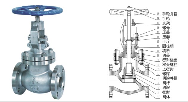
1-body; 2-sealing; 3-disc; 4-stem; 5-disc nut; 6-screw nut; 7-back sealing; 8-stud; 9-sealing gasket; 10-bonnet; 11-stuffing; 12-pin; 13-bolt; 14-bushing; 15-gland; 16-screw; 17-yoke; 18-handwheel; 19-handwheel nut
4.1 Disc
□ balance-single disc □dual discs □plunger type □other
sealing face welding □ 13Cr □ CoCrW □ other
Disc moving up and down along center line vertically
4.2 Seat
□ welding connection □ threaded connection □ other
sealing face welding □ 13Cr □ CoCrW □ other
4.3 Stem
stem design: □ non-rising □ rising □ other
4.4 Flange end connection:
□ flange □ grooved □ welding
4.5 Stem sealing
□stuffing + seperating ring □stuffing + soft packing □ O-Ring □other
□stuffing
4.6 Operation
□manual □electric □pneumatic □hydraulic □other
4.7 Connection
□flange □welding □other
When manual operation, clockwise is close, anticlockwise is open. Other driving type as instruction for avoiding mistake.
5 Main parts and material
S/N | NAME | MATERIAL | ||
CARBON STEEL | ALLOY STEEL | STAINLESS STEEL | ||
1 | BODY | □ WCB □ LCB □ other | □ WC6 □ LC3 □ WC9 □ other | □ CF8 □other □ CF8M □ CF3 □ CF3M |
2 | BONNET | □ WCB □ LCB □ other | □ WC6 □ LC3 □ WC9 □ 其它OTHER | □ CF8 □other □ CF8M □ CF3 □ CF3M |
3 | DISC | □ WCB □ LCB □ other | □ WC6 □ LC3 □ WC9 □ other | □ CF8 □ other □ CF8M □ CF3 □ CF3M |
4 | STEM | □A182-F6a □A182-F304 □A182-F304L □A182-F316 □A182-F316L □17-4PH □OTHER | ||
5 | BOLT/SCREW | □ 35CrMoA/45 □ 42CrMo/20CrMo □ 0Cr18Ni9Ti/0Cr17Ni12Mo2 □ OTHER | ||
6 | STUFFING | □ PTFE □ SOFT GRAPHITE □ RUBBER RING □ OTHER | ||
7 | GASKET | □ PTFE □ SOFT GRAPHITE + STAINLESS STEEL □ STAINLESS STEEL □ OTHER | ||
6 Installation and usage
6.1 installation
6.1.1 Installation position for convenient to operate and maintain
6.1.2 Make sure that the size, performance specification, technical requirement, nameplate marking, installation direction and etc available to using condition, especially right installation direction before valve installed.
6.1.3 Clean the cavity, clear the impurity, stains and rust.
6.1.4 Make sure the flange screw and gland tight, valve off-on is convenient.
6.2 Usage
6.2.1 Valve just works as off and on, not suitable to adjust. Exceeding temperature, pressure and frequent changing pressure is not allowed. Tight the screw in regular time when valve working in high temperature for avoiding leakage, reducing heat gradient. It is not allowed that impact load and high stress concentration occurs when valve working in low temperature.
6.2.2 Add lubricating oil, sealing compound and soft stuffing in regular time when valve with oil choke, sealing compound and stuffing filler plug device. Make sure that valve works well.
6.3.3 When manual operation, clockwise is close, anticlockwise is open. Other driving type as instruction for avoiding mistake.
7 Maintenance and storage
7.1.1 Inspect and maintain valve in regular time, avoiding rust and jamming, keeping valve in good condition.
7.1.2 Inspect the bonnet loose or not if stuffing box leakage, tight bonnet again if loose. Release pressure when replace stuffing.
7.1.3 Inspect the fastening bolt loose or not if flange leakage. Inspect gasket damage or aging or not, or sealing face damage or not if still leakage, replace gasket and amend sealing face.
7.1.4 Inspect the valve closing in right position or not, impurity or not if sealing face inside leakage. Close and open valve one time to verify if permission.
7.1.5 Valve inspect and maintain, washing parts, replace damaged stuffing and gasket, amend sealing face if the leakage can not be resolved as 7.1.2,7.1.3,7.1.4. Reset the relieving pressure if the valve with safety relieving device. The pressure is less than 1.1 times temperature-pressure rated value, Reuse valve after water test passes.
7.1.6 Break down and eliminate method
Fault Phenomenon | Reason | Resolve |
Stem can not turn | Stuffing pressed tightly over | Loose the screw , readjust |
Damage between stem and other parts or exist impurity | Disassembly and amend, clear the impurity
| |
Off and on times over | ||
Sealing face leakage | Tight not enough | Tight more |
Damage or impurity on sealing face | Amend sealing face and clear impurity | |
Sealing face transformation or lose efficacy | ||
Stem packing leakage | Stuffing pressed tightly not enough | Replace the screw and bolt |
Stuffing used too long and lose efficacy | Replace stuffing | |
Flange leakage | Flange screw loose | Tight the screw again |
7.2 Storage
7.2.1 Storage in dry warehouse, forbidding stack and open storage.
7.2.2 Both flange ends add capping, use oil paper to protect stem bare section for avoiding impurity damage the sealing face.
7.2.3 Maintenance in regular time if long storage, clear impurity, spot and rust. Recoat rust-proof oil.
8 NOTES
8.1 Valve material selected and material gets worse, regular time inspection by customer.
8.2 Pls make a note in the contract if any special requirement. Valve design as normal using condition.
8.3 Valve design just suits slight corrosion, serious or special corrosion environment not available.
8.4 Valve work temperature can not exceed performance specification, or the result by customer.
8.5 Set warning mark in suitable position because the valve surface high temperature will lead people body scald when the valve working
8.6 Welding and paint not allowed when the valve working.
8.7 Disassembly not allowed when the valve in pressure.
8.8 Amend as the 4 rules material sheet matching the parts.
8.9 The valve wall thickness design consider thickening and safety factor. Pls note that water hammer pressure occurs when close valve.
8.10 Inspect and replace in regular time by customer is necessary.